Welcome to the CU Sounding Rocket Lab Docs
Welcome to the CU SRL Avionics Documentation!
If you are not yet a member of the CU SRL, please visit our site, at https://cusrl.com/, for more information on getting involved. You can also check out any pages on this site called "Getting Involved" under each of the sub-teams.
Editing the docs
Our documentation system is hosted on GitHub Pages, and uses Markdown files to show content.
To edit the documentations, you may either:
- Clone the git repository these documents are hosted on, and edit using an editor of your choice.
- Edit the docs directly on GitHub, and commit your changes there.
If you're going to be doing a lot of editing, we recommend the first option. Otherwise, click the "Edit" button on the top right of a page to edit it directly on GitHub. You may also add new pages on GitHub itself.
Cloning the repository
First, you must be added to the Github SRL organization. Get in touch with a team leader to do this.
Next, clone the repository.
For first-time Git users, we recommend you use GitHub Desktop, with an editor of your choice (such as Visual Studio Code).
For command line users, or those who want to familiarize themselves with git, use the following command in a folder of your choice:
git clone git@github.com:CU-SRL/docs.git
then open the documentation in an editor.
Uploading changes
Using GitHub Desktop, simply add a change summary, commit, then push to the main branch.
Using command-line git, navigate to the repository folder, then
git add .
git commit -m "<change description>"
git push origin main
Working with the documentation
The documentation root looks like this.
book/           The theme and styling of the website itself.
src/            The folder containing site content.
book.toml       Backend parameters for the site generator.
Most of the work you'll be doing will be inside the src/ folder.
Working with Markdown
GitHub has good documentation on working with Markdown, available here.
There is also a guide specific for this book available on the mdBook documentation, with some unique features like strikethrough text and table syntax.
Structure
The documentation inside the src/ folder is structured as shown below.
SUMMARY.md
avionics/
- currentprojects/
    - currentprojects.md
    - testboard.md
- overview/
    - images/
    - overview.md
    - ...
- gettinginvolved.md
All pages are Markdown (.md) files.
Section headings are folders. Inside each folder, you might find some subheadings. If you want a subheading to be clickable, create that subheading inside its folder (such as overview/overview.md).
We recommend you explore a bit and get familiarized.
Adding a page
First, create the .md file for the page you want to create.
Then, create a link to that Markdown file inside the SUMMARY.md file. Look inside SUMMARY.md for examples.
Removing or moving a page.
Modify the relevant page, and make sure to update SUMMARY.md accordingly to redo the link to that page.
Working with images
To add an image to a page, create an images/ folder if it does not already exist, in the same directory as the page you want to add an image to. Copy the image to that images folder.
Then, inside the .md file, use Markdown image syntax to link to it. Links are relative, so use images/your-image.png for the link.
If you want to resize your image, use the following syntax instead:
<img src="images/your-image.png" width="150" height="280">
Mission Statement
The mission of SRL Avionics is to create a reliable avionics system capable of verifying that a rocket has reached space while building a supportive community which develops us as engineers. We welcome members of all skill levels and are dedicated to using rocketry avionics as a way to deepen our technical ability.
Meeting Time
Join us every Wednesday at 6:30PM in ECEE 220!
CU Sounding Rocket Laboratory Website Link
Join the SRL Slack and Notion!
- Slack Invite Link
- Notion Invite Link - Coming Soon
Leads
Reach out to leads for any questions you may have!
Alex Reich alre8317@colorado.edu - Avionics Lead
Pranith Bhat pranith.bhat@colorado.edu - Avionics Controls Lead
Owen White owen.white@colorado.edu - Avionics Embedded Software Lead
Fedor Bezzubtsev fedor.bezzubtsev@colorado.edu - Avionics Hardware Lead
Landon Holligan landon.holligan@colorado.edu - Avionics Structures Lead
Getting Involved!
Ready to get involved? Follow these steps!
- Do everything on the new member checklist. Joining the slack is especially important, as all meeting announcements and general discussions happen there!
On the slack, join the following channels:
#avionics#avionics-hardware#avionics-software#avionics-bay
-
Browse through the avionics resources, and see what looks interesting to you.
- Take a look at our common practices page to get more familiar with our typical architecture. Although we try to be as beginner-friendly as possible, we do use some jargon so reading through this page will help you get a leg up!
-
Reach out on Slack to the current avionics team lead (Alex Reich) or the sub-team lead with the topic you're most interested in (embedded software, web development, controls/state estimation, structures, RF, or PCB design) to see where you can get started.
The leads will have a list of things you need to do to get set up with the team, ask about this! Also let them know how much experience you are coming in with so they can cater the onboarding process to you individually.
Jot down the time and date of the next avionics meeting in your planner! (Also should be on the central page)
This is a page for avionics members to list out resume and career tips!
First off, feel free to reach out to your avionics lead if you want to meet 1-on-1 for resume advice or a mock interview or even simply resume advice. Your sub-team leads and team lead will always be willing to help you out, and you can gain a lot of meaning from getting feedback from peers on your resume. This will be a page that gets updated as time moves forward, and hopefully it can be a great additional resource for your professional development!
Things to consider:
- What is the culture of the company you are applying for and what skills are valuable for the role?
- Your resume should be tailored to the company you are applying to and the specific job posting.
- Companies like SpaceX and Blue Origin want to see ownership on your resume. What were YOU 100% responsible for? You should be able to talk about the parts of the project you owned in extreme depth, and be able to answer any question possible about them.
- If you are applying to a SWE role, your resume should not stay the same as if you are applying to an EE role. Use detailed terms in your bulletpoints (i.e. "STM32", "designed in Altium", etc.) to get past the ATS checkers for the specific role that you are looking for. For example, a software role probably doesn't care if you know how to use OpenRocket.
- Your resume should be tailored to the company you are applying to and the specific job posting.
- General Stuff
- You should not have more than 4-5 bulletpoints for each experience
- Class projects generally do not make you stand out, since everyone else in your class probably did a similar project. Unless your project was far above the level of everyone else's, a club project or research experience is always more impressive.
- Your employer unfortunately does not care what your hobbies are. If they are curious they will ask during the interview, but on a one page resume every line should be used to convey technical ability.
- Your resume should be one page only. In college you do not have enough experience to warrant anything more, and recruiters do not have the time to read through two pages of fluff.
- Do not make up statistics just because you think you're supposed to. In a technical round you will be asked about how you "increased efficiency by 25%", and if you didn't really do that they will see it from a mile away. It is better to represent yourself accurately and honestly, and trust that the right job will come your way.
- Represent your technical achievements at a high level. In other words, do not specifically say "Wrote a function that wrote 8 bit values to a configuration register over SPI for the TMC429". Instead, think more along the lines "Wrote custom driver to control the TMC429 motor driver over SPI in C". They will ask you about the details in the interview-- use the space to include more high level ownership.
- Keep your bulletpoints short. Each one should not take up more than 2 lines.
- Start bullet points with action verbs. "Owned", "Led", "Executed", etc.
Notes on making connections:
- Coming soon
SRL AVIONICS RESOURCES
These documents contain information that we have gathered over the past few years of working with the tools that we commonly use. Use these as a reference to help clear up confusion and move past roadblocks!
- Git/Version Control resources
- Zephyr resources
- Embedded systems resources
- PCB resources
- Structures resources
- RF resources
SRL Avionics Common Practices
SRL Avionics tends to use similar components and frameworks across lots of different projects. This helps build expertise and decrease development/debug time, allowing us to build our skills and projects faster.
Microcontrollers:
SRL Avionics loves the STM32 line of microcontrollers. With a large selection of different specifications, there is typically an STM that is applicable for any project. It also has great documentation and wide support across software frameworks, as well as a useful HAL (Hardware Abstraction Layer) that can be used in Zephyr in addition to higher level APIs.
Typically, for "smarter" applications requiring complex matrix operations, we use an MCU in the STM32H7 line. These can have up to 208 pins and are used on the Liquids Data Acquisition System (DAQ). For "dumber" applications that simply control a peripheral we use an MCU from the STM32F4 line. These can have as low as 32 pins and are used on applications such as a stepper controller or a radio board.
Embedded Frameworks
We typically use the Zephyr RTOS for almost every project. Its API is extremely well documented, and it has prewritten drivers for a wide variety of communication protocols, sensors, and various other peripherals. This makes it much more beginner friendly, and speeds up the pace of development significantly. It can be a bit finicky when it comes to hardware abstraction in the devicetree, but documentation can usually straighten things out. In addition, our resources document common issues we've faced in the past, so we can move past many problems quickly. All of our software-based leads have at least a year of experience with Zephyr, and can help you debug as well!
Programming Languages
Avionics almost always uses C or C++ for embedded applications. It is well documented and is very beginner friendly, allowing new members to jump in quickly. Python is also occasionally used for higher-level programming on a Raspberry Pi or computer, and MATLAB is typically only used for post-flight data processing.
PCB Design Software
Electrical engineers in SRL avionics use Altium, and do version control using GitHub repositories inside the CU SRL organization. Altium is widely used in industry and is a very valuable skill to have on your resume. In addition, it is well documented with lots of informative tutorials on YouTube. CU Boulder provides a free student license, and we believe that everyone interested in PCB design should take advantage of this to build skills before entering industry.
Computer-Aided Design (CAD)
Across all subteams (not just avionics), SRL uses a shared Fusion360 drive. Any CAD relating to a core project (Spaceshot, Liquids Engines/Vehicles, etc.) must eventually end up in the shared F360 drive to be saved for posterity. DM the current team captain to be added.
Communication Protocol
To communicate between nodes in a distributed embedded system such as SRL's ground station or avionics bay, we typically use RS422 with RJ45 (Ethernet) connectors. It is easy to buy shielded harnesses with these connectors which is useful when routing near high-power RF systems. See more details on RS422 on the (communication protocols)[../embedded/comm_protocols.md] page.
SRL Avionics Project Development Cycle
The objective of this page is to provide a clear blueprint to guide the team through project conception to completion.
Stage 1: Conception
In order for a project to be successful, it must have predefined
- Motivation
- Scope
- Requirements
Before a project can pass this stage, these 3 things MUST be fully defined and agreed upon by the project lead (and if relevant the team captains).
This stage is also where research on the current field is conducted. Questions that should be answered include
- Is there a COTS solution?
- If so, can we use it or modify it?
- If not, is it because it has yet to be done, or because there is a better way to achieve the stated goal?
- Have other student rocketry teams done something similar?
- If so, what challenges did they face? How can we address those problems from the start to come up with a better solution?
- If not, who could we reach out to for guidance? Are there professors at CU who would be willing to advise?
- Is the high-level system architecture/con-ops even feasible?
- Are the interfaces possible/do they make sense?
- Do the laws of physics allow the requirements to meet without compromising each other? (this is where link budget analysis, power budgets, weight restrictions, etc. come into play)
- Does the club have the institutional knowledge to design, build, and test a system with the proposed complexity?
- The simpler the project is, the higher the likelihood of completion.
This stage concludes with a Preliminary Design Review (PDR) (guidance on this presentation coming soon). Project leads should encourage other unrelated members of the club to participate, as multidisciplinary opinions can often catch overlooked design flaws.
PDR Guidance
This stage should last 1-2 months, depending on the complexity of the project. It is important to leave this stage relatively quickly both to capitalize on momentum and to get to the prototyping stage as quickly as possible.
Stage 2: Design
Once the project has passed PDR, club resources can be devoted to the project's development. Work should start on any relevant software, PCBs, or structural hardware in parallel to avoid one specific area being in the critical path.
- Avoid the temptation to wait on software development for the PCB to be done. Often, the software development takes much longer than hardware design, so the project will suffer delays if software dev is not started immediately. This is why infrastructure such as unit testing and breakout boards for peripherals are extremely valuable.
- This is why defining strong requirements and interfaces in the coneception stage is important. A common source of truth will allow hardware and software teams to understand what the other needs to do, which will avoid blockages while one waits for the other.
As soon as the project enters the design phase, Responsible Engineers should be appointed to own every major aspect of the project (i.e. software, PCBs, antenna design, structures/mechanisms design). These REs will commit to seeing through their part of the project until completion, and will often be the members driving the project through the conception stage.
- Avoid giving an RE role to someone who has not demonstrated personal investment in the project. Ownership is something that must be intrinsically motivated, so everyone will have a better time if the person responsible for each subsystem comes to work sessions often and communicates well.
This stage is where rapid, cheap prototyping should occur. 3D printing and cheap parts off Amazon or McMaster are perfect for this, enabling the REs to determine the actual feasibility of the project as quickly as possible.
Before major POs are placed, an informal Design Review should be held. These are meetings where the RE can present their work on a subsystem to other members of the club (often not in the same subteam). These meetings help to iron out inconsistencies in the design and serve as a filter to make sure only the most robust ideas make it through to the end product.
This stage should culminate in a Critical Design Review (CDR). By the time of the CDR, the PCB must be fully designed, the software must be largely written, and the low level implementation details of the project must be resolved. PCBs/expensive mechanical components should not be ordered before the project has passed a formal CDR.
The CDR will be a formal presentation, detailing the low-level implementation details. The RE for each subsystem will present their portion, and feedback will be encouraged from the rest of the team.
CDR Guidance
The design stage for a project should take about a semester. Be wary of extending past this timeline except in specific cases or extremely complex projects. Momentum is very difficult to carry between semesters, especially over the summer, and the effect of losing this momentum should not be underestimated.
Stage 3: Assembly, Integration and Test
After CDR is passed, the project is fully greenlit. PCBs and components for any relevant structures should be ordered.
- Any large system shall have a BOM with a list of all parts for future reference, which will be a requirement before the avionics lead will place POs.
- Any machined components shall have associated drawings in compliance with the drawing guidelines to help machinists
- Any PCB will also have an associated schematic and layout review before ordering
Components should all be ordered together, and marked off on the BOM when they are recieved. The team will assemble the project and begin to test the software. This stage is considered flight ready once testing concludes that the initial system requirements have been met.
Git Version Control Basics
Topics:
- SRL Software Development Workflow
- Git CLI tool install
- Helpful commands
SRL Avionics Software Development Workflow with GitHub
Resources for Embedded Systems
Topics:
- What is an embedded system?
- Application architecture
- Communication protocols
- Polling, Interrupts, and DMA
- Distributed embedded systems
What is an Embedded System?
Everyone interacts with embedded systems countless times every single day. Anything from your refrigerator to your car can be an embedded system. The line between what is and isn't an embedded system is blurry, but generally the idea is that an embedded system has constrained resources, low(ish) size, weight, and power (SWaP), and is designed for a set of defined applications. Think garage door opener or microwave as opposed to a laptop.
Most of what avionics does is build and test various forms of embedded systems. Our flight computer, gimbal controller, and all of our radios qualify.
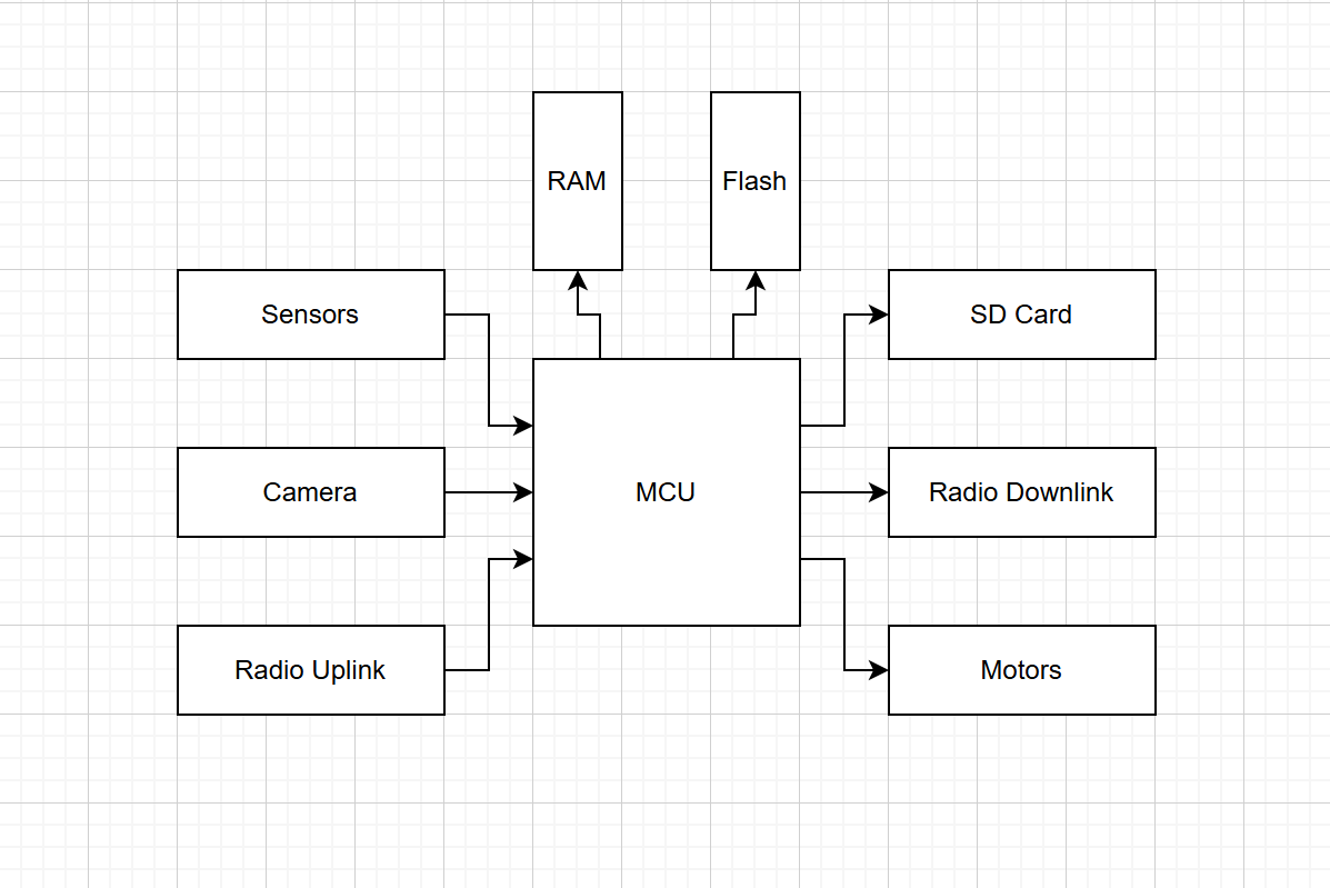
Typical Architecture
A typical embedded system consists of a central MCU (Microcontroller Unit), which communicates with peripherals (electronic devices like sensors, level shifters, drivers, or other embedded systems). Below is an image with some example peripherals.
Resources for software development with ZephyrRTOS
Topics:
- ZephyrRTOS installation process (for Windows, Mac, Linux)
- Interfacing with peripherals using Zephyr
- Includes examples for GPIOs, I2C devices, SPI devices, UART devices, and sensors
- Using threads with Zephyr
- Common issues + solutions
- Building and flashing an application to your MCU
- Making a new Zephyr project
- Unit testing with Zephyr
Zephyr RTOS Setup Guide
Zephyr is a scalable real-time operating system designed for resource-constrained embedded devices. It supports a wide range of ARM Cortex-M targets — including STM32 and Nordic nRF series — which are commonly used in avionics hardware.
These scripts automate the full installation of the Zephyr SDK, the west meta-tool, and all required dependencies.
Note:
- Summary written by AI
- Any time
zephyrprojectis mentioned, it can be replaced with the top level directory of your project.
Quick Start
| Platform | Script |
|---|---|
| Linux (Ubuntu, Fedora, Arch) | install_zephyr_linux.sh |
| macOS (Intel and Apple Silicon) | install_zephyr_mac.sh |
| Windows (Git Bash + Chocolatey) | install_zephyr_windows.sh |
Platform-Specific Instructions
Linux
Prerequisites: sudo access is required to install system packages.
chmod +x install_zephyr_linux.sh
./install_zephyr_linux.sh
Supported distributions: Ubuntu, Debian, Linux Mint, Pop!_OS, Fedora, Arch, Manjaro.
macOS
Prerequisites: The script will install Homebrew automatically if it is not present. Accept the Xcode Command Line Tools prompt when asked.
chmod +x install_zephyr_mac.sh
./install_zephyr_mac.sh
Works on both Intel (x86_64) and Apple Silicon (arm64) Macs.
Windows
Windows support is provided through Git Bash (included with Git for Windows) and Chocolatey.
Step 1: Install Chocolatey (run once from an Administrator PowerShell)
Set-ExecutionPolicy Bypass -Scope Process -Force
[System.Net.ServicePointManager]::SecurityProtocol = 3072
iex ((New-Object System.Net.WebClient).DownloadString('https://community.chocolatey.org/install.ps1'))
Step 2: Run the script from Git Bash (not PowerShell or cmd.exe)
chmod +x install_zephyr_windows.sh
./install_zephyr_windows.sh
WSL2 alternative: If you have WSL2 installed, running
install_zephyr_linux.shinside a WSL2 Ubuntu shell is generally more reliable than the Git Bash approach. See Microsoft's WSL2 guide for setup instructions.
What the Scripts Do
Each script performs the following steps in order:
- Install system packages — cmake, ninja, gperf, device tree compiler, Python 3, and other build tools via the platform's package manager.
- Create a Python virtual environment at
~/zephyrproject/.venvto isolate Zephyr's Python dependencies from the system. - Install West — Zephyr's meta-build tool, used to manage the workspace and build firmware.
- Initialize the Zephyr workspace at
~/zephyrproject/by cloning the Zephyr repository and all required modules. - Install Zephyr Python requirements from
zephyr/scripts/requirements.txt. - Download and install the Zephyr SDK — the cross-compilation toolchain for your target architecture.
- Persist the venv activation in your shell profile (
.bashrc,.zshrc, or.bash_profile) so the environment is available in future terminal sessions.
Configuration
All scripts respect the following environment variables, which you can set before running to override defaults:
| Variable | Default | Description |
|---|---|---|
ZEPHYR_SDK_VERSION | 0.16.8 | Zephyr SDK version to install |
ZEPHYR_BASE | ~/zephyrproject | Where to initialize the Zephyr workspace |
ZEPHYR_TOOLCHAIN | arm-zephyr-eabi | Which cross-compiler toolchain to install |
Example — install a specific SDK version and all toolchains:
ZEPHYR_SDK_VERSION=0.16.8 ZEPHYR_TOOLCHAIN=all ./install_zephyr_linux.sh
Common toolchain values:
arm-zephyr-eabi— ARM Cortex-M/R (STM32, nRF, most avionics MCUs)riscv64-zephyr-elf— RISC-V targetsxtensa-espressif_esp32_zephyr-elf— ESP32all— every supported toolchain (~7 GB download)
For most avionics work targeting STM32 or Nordic nRF MCUs, the default
arm-zephyr-eabitoolchain is sufficient.
Verifying the Installation
After the script completes, open a new terminal and run:
source ~/zephyrproject/.venv/bin/activate   # Linux/macOS
# or
source ~/zephyrproject/.venv/Scripts/activate  # Windows Git Bash

west --version
cmake --version
You should see version output for both tools with no errors.
Building Your First Project
The standard Zephyr workflow uses west build to compile firmware for a specific board target.
# Activate the Zephyr environment
source ~/zephyrproject/.venv/bin/activate

# Navigate into the Zephyr source tree
cd ~/zephyrproject/zephyr

# Build the hello_world sample for your board
west build -b <board_name> samples/hello_world

# Flash the firmware (requires a connected programmer)
west flash
Common board targets:
| Board | Zephyr target name |
|---|---|
| STM32 Nucleo-F401RE | nucleo_f401re |
| STM32 Nucleo-L476RG | nucleo_l476rg |
Run west boards to list all supported targets, or search at docs.zephyrproject.org.
Pinning a Specific Zephyr Version
To use a specific Zephyr release instead of the latest, pass --mr to west init:
west init --mr v3.7.0 ~/zephyrproject
Zephyr releases follow the pattern v<major>.<minor>.<patch>. Check GitHub releases for available versions.
Troubleshooting
west: command not found after installation
The virtual environment is not active. Run:
source ~/zephyrproject/.venv/bin/activate
west update fails mid-way
Network interruptions can leave the workspace in a partial state. Re-run west update — it is idempotent and will resume where it left off.
SDK setup fails with permission errors (Linux)
Ensure ~/zephyr-sdk-<version>/ is owned by your user, not root. Re-run the SDK setup step manually:
cd ~/zephyr-sdk-0.16.8
./setup.sh -t arm-zephyr-eabi -h -c
Homebrew not on PATH after install (macOS Apple Silicon)
Add this to your ~/.zshrc:
eval "$(/opt/homebrew/bin/brew shellenv)"
CMake can't find the Zephyr package
Run west zephyr-export from inside the workspace directory:
cd ~/zephyrproject
west zephyr-export
Windows: 7z not found
Install 7-Zip via Chocolatey from an Admin shell, then reopen Git Bash:
choco install 7zip
Further Reading
Interfacing with peripherals in ZephyrRTOS
Topics:
GPIOs
STEP 1: Setting up the devicetree:
In Zephyr RTOS, the easiest way to configure hardware interface with the gpio is to add the following to your app.overlay file
/ {
    ...other configs here...

    zephyr,user {
        your-gpios = <gpioa 1>;
    };
}

&gpioa {
    status = "okay";
}
This example would define GPIO A1. Setting status = "okay" tells Zephyr to enable GPIO bank A, and the zephyr,user code defines the specific GPIO that you want to access (bank A, pin 1). When you do this for your own code, talk to whoever designed the PCB to see what GPIO bank and pin you should use.
STEP 2: Access the device in your C/C++ code:
Then, in your code, you can access that node in the following way:
#include <zephyr/drivers/gpio.h>
#include <zephyr/logging/log.h>

LOG_MODULE_REGISTER(gpio_sample, LOG_LEVEL_INF);

// define the gpio device in your C/C++ file
#define USER_NODE DT_PATH(zephyr-user)
static const struct gpio_dt_spec your_gpio = GPIO_DT_SPEC_GET(USER_NODE, your-gpios);

int your_function() {
    //check if the gpio device is ready
    if (!gpio_is_ready_dt(&your_gpio)) {
        LOG_ERR("GPIO not ready");
    }

    //configure the gpio pin (in this case, it is output and active high)
    int ret = gpio_pin_configure_dt(&your_gpio, (GPIO_ACTIVE_HIGH | GPIO_OUTPUT));
    if (ret < 0) {
        // failed
        LOG_ERR("Failed to configure gpio: %d", ret);
    }

    // now that the gpio is initialized and configured, you can toggle it or set it arbitrarily!

    // toggle gpio:
    gpio_pin_toggle_dt(&your_gpio);

    // set gpio high:
    gpio_pin_set_dt(&your_gpio, 1);

    // set gpio low
    gpio_pin_set_dt(&your_gpio, 0);

    return 0;
}
Sensor API
I2C Devices
ADCs
SPI Devices
UART (Interrupt Based)
UART (DMA Based)
Spawning and Using Threads in ZephyrRTOS
PCB Resources
Topics:
- Basics of electrical engineering (Frequency response, impedance, op-amps, pull-up/down resistors, ESD protection, transistors)
- SRL Avionics PCB standards
- PCB assembly and bring-up procedures
- SRL Avionics heritage designs (DC-DC Converters, Sensors, MCUs + more)
Heritage designs for future use
Power Circuitry
Buck Converters
LDOs
Sensors
MCUs
GPS
We like the u-blox Neo-M8 line generally. There are a lot of drivers available, and the layout is relatively easy. Here is the reference manual which has sample schematics, etc.
Common PCB Standards for SRL Electronics
General
Unless there is a specific engineering reason, components should only be placed on one side of the board. This makes assembly dramatically easier and faster, and removes risk of damaging components on the bottom during integration.
Debug Capability
All PCBs that use an STM32 shall use the JLink connector, which connects to the SWD interface on the chip. This allows the software team to use the RTT viewer for debug messages, and in our experience is the easiest way to debug and flash the board.
In addition, each PCB should expose a 7-pin male header row which is connected to a debug UART. This is useful because it can be used as a sort of console which can be used to send commands to the board during testing. In addition, if the board uses RS422 (which most of ours do), the software team can test their parsers and command handlers before the rest of the distributed system is ready.
Power Systems
All inputs to the board (RS422 ports, UART ports, analog/digital inputs, etc.) must have ESD protection diodes.
Silkscreen
All PCBs shall have the SRL logo placed somewhere on top layer silkscreen. Optionally, the designer can choose to include their own name and any other names of people who helped on the project on either side of the board.
How to bring up a PCB
So you've designed, laid out, ordered, and assembled your PCB. How do you bring life to it?
Steps
Structures Resources
Topics:
- Creating Drawings
- Tolerancing Guidelines
- Design for Manufacturing Guidelines (DFM)
Drawings
Before going to manufacturing,
- Every flight part shall have an associated drawing signed off by a lead
- This drawing shall be stored in the OneDrive for future reference
- Proper tolerancing guidelines shall be observed
Resources for RF engineering
Topics
- Basics of RF (Fourier Transforms, Gain, Link Budgets, Bandwidth/Bitrate relationship)
- Basics of Antennas (Gain Pattern, Polarity, Smith Charts, Antenna Tuning)
- RF Front End (RFFE) High Level Design (Filters, Amplifiers, Mixers, PLLs, ADCs, DACs)
- RF Layout (Impedance profiles, Hybrid couplers, Rat-race couplers, Stripline/Patch antennas)
- RF Component Choice (Amplifier characteristics, filter characteristics)
- Phased Arrays (Array factor, Beam Steering, Angle of Arrival)
- ANSYS EDT HFSS Resources
Basics of RF
Signals and Fourier Transforms
At its very core, RF communications is about transmitting information from one location to another. The information is transmitted by creating varying electric and magnetic fields, which are able to propagate, but we'll come back to that later. For now, lets talk about how we can turn integers, voice signals, or video streams into these varying fields.
Due to the field propagation mentioned above, RF signals need to be a time-varying AC voltage. The simplest example of this is a sinewave, which can be represented as
$$ x(t) = A\cos(2\pi f_0t + \phi) \tag{1}$$
where $f_0$ is the frequency of the signal, $\phi$ is the phase shift of the signal, and $A$ is the amplitude of the signal. This sinewave looks like this:
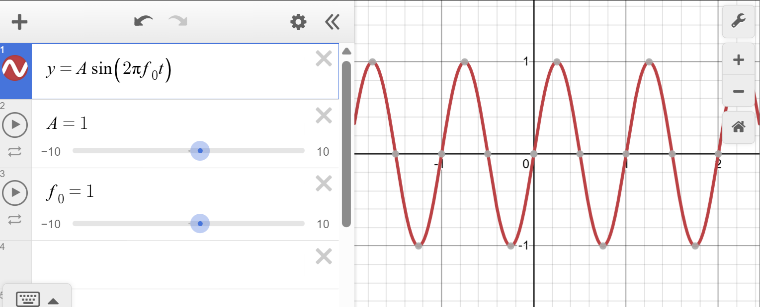
Changing $A$ will increase or decrease the "height" of the sinewave. Increasing $f_0$ will scrunch the signal together, and decreasing it will spread it out. Lastly, changing $\phi$ will shift the signal back and forth. These three quantities are the levers that we can pull in order to "encode" data into the signal (there are other things too but those are more complicated so we will ignore those for now).
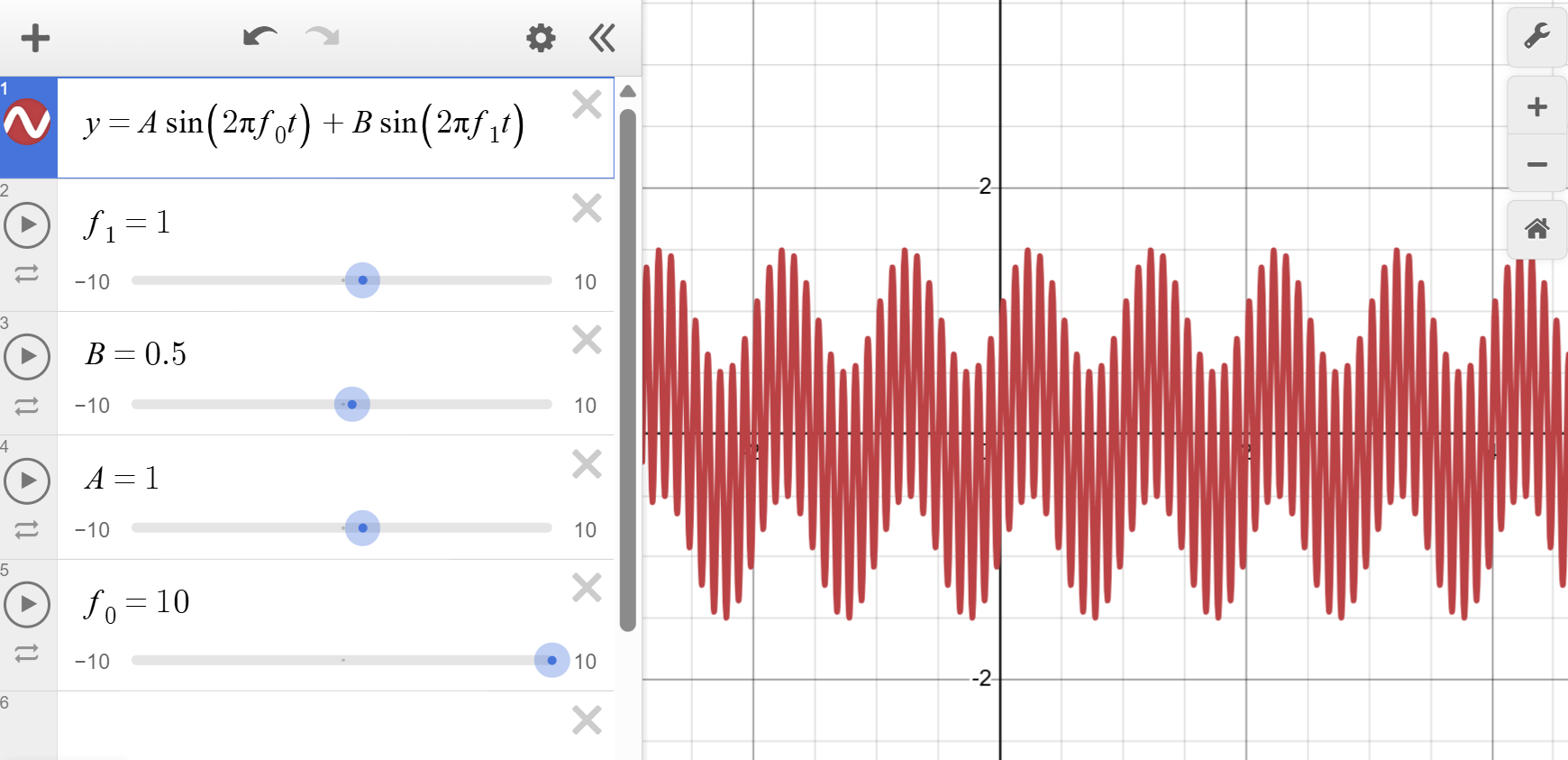
The first and simplest method we will discuss here is amplitude modulation, or AM for short. If you've ever heard of AM radio, this is exactly what that is. Essentially, we can encode information in the signal by changing it's amplitude over time. The way we do this is by designating a carrier frequency which serves as the frequecy who's amplitude will be changed, and adding a message frequency which represents the data you are trying to send. In the end, the signal looks something like:
$$ x(t) = A\sin(2\pi f_c t + \phi _c) + B\sin(2\pi f_m + \phi _m) \tag{2}$$
where $B$ is the amplitude of the message frequency, $f_m$ is the message frequency, and $\phi _m$ is the phase of the message frequency. This signal ends up looking like this:
This leads us nicely into the idea of...
The Fourier Transform
Coming soon...
$$ G_{eff} = \eta \frac{4\pi A_0}{\lambda _0^2} $$
$$ \eta_{petals} = e^{-(\frac{2.08 \frac{D}{\lambda}}{N^2})^2} $$
Basics of Antennas
Table of Contents
The purpose of an antenna is to radiate the signal generated by a modem through space. It does this by creating a varying electric/magnetic field. The shape, size, and materials of an antenna and its surroundings all change the behavior of this propagation.
There are many ways to characterize an antenna's radiative properties. These include the gain pattern, the Voltage Standing Wave Ratio (VSWR), the antenna parameters (S11, S12, S21, S22, etc.).
Gain Pattern
The gain of an antenna is measured in directivity, with units of dBi. As we know, decibels are always some sort of ratio. In this case, it is the ratio of the ability of a given antenna to focus energy in a specific direction compared to a theoretical isotropic radiator.
Imagine you have a bare lightbulb, with nothing covering it. It will shine light equally in all directions. This is analogous to an isotropic radiator. Now imagine that you put that lightbulb inside a flashlight. Now, all of a sudden, all of the energy from the lightbulb is redirected in one direction, and can illuminate a smaller area much brighter. This is exactly what antenna gain is. You're not making the bulb any brighter, but you're focusing the energy that is available to you into a smaller spot.
In this analogy, the geometric properties of the flashlight beam would be the gain pattern. Things like how wide the cone of light is and the angle at which the brightness decreases to a certain amount are the benchmarks that are typically used for antennas. The most common one is the Half Power Beamwidth or HPBW.
The HPBW is the angle at which the magnitude of the signal being transmitted reaches -3dB from its max. {INSERT PICTURE EXAMPLE HERE}
Propagation
Antennas radiate by creating electric fields. The best way to do this is to be able to group charge into one side at a time, and have it move cleanly from one end of the antenna to the other. For example, in a $\frac{\lambda}{2}$ dipole antenna, the goal is to generate a voltage standing wave such that at any given moment, the voltage at one end of the dipole is exactly the opposite of the voltage at the other end.
Lets examine this a little closer. Take the case where the right of the antenna is negatively charged, and the left end is positively charged. In this scenario, the electric field lines will create paths traveling from the left end to the right end. Next, if we let the wave oscillate until the charge has switched position, the electric field will point in the exact opposite direction, going from the right to the left. We've just created an oscillating field! Because changing electric fields and changing magnetic fields sustain one another, part of that near-field energy propagates away from the antenna as an electromagnetic wave.
The higher the ability for the antenna to create these standing waves, the better it will be at radiating energy. This perfect standing wave described above would only happen when the antenna is in resonance-- in other words, when the wavelength of the signal exciting the antenna is exactly equal to two times the length of the dipole. If this is not the case, it doesn't mean the antenna can't radiate. It simply means that the resonance will not be as strong, and some of the energy will be lost due to reflections.
VSWR is a measure of how well this resonance is able to take place for a given frequency and antenna. {MORE DETAILS COMING SOON}
Polarity
Polarity is simply a description of the axis in which the electric field is oscillating. The $\frac{\lambda}{2}$ dipole I mentioned earlier is an example of linear polarization. This means that the field is oscillating up and down or side to side. Other types of polarization include dual polarization (both side-to-side and up-down at the same time) and circular polarization (the wave oscillates in a spiral).
For a physical example of what this means, imagine you have a rope, and you are pulling the rope up and down and making a wave. If you simply move it up and down, it will oscillate in that vertical plane, and someone on the other end could measure the vertical position of the rope at a given time to measure the "signal" you are sending. If you moved the rope instead so that it is oscillating side to side, a person on the end would need to measure the horizontal position of the rope to see the signal. If they tried to measure your signal by measuring the up-down motion while you are moving the rope side to side, they will not see anything. This is the same exact way that RF polarization works.
An antenna's polarization typically stems from a combination of geometry and how the antenna is excited. Examples of linear polarization include dipoles, monopoles, and certain Yagi antennas (to name a few). Dual-polarized antennas include turnstile (or crossed dipole) antennas, and circularly polarized antennas include helixes and some horn antennas. Patch antennas can be made to be linear, circular, or cross-pol which is why they are a common choice.
Impedance Matching
Coming soon
Antenna Parameters
Related to VSWR and impedance matching, antenna parameters can give you additional information that can help you design and tune an antenna for optimized radiation.
- $S_{11}$
This parameter describes the
Common Antenna Types
Dipole
The most common type of antenna is the dipole.
Monopole
Helix
Horn
Patch
Arrays
Optics
Current Projects
Avionics is currently working on a number of projects in parallel.
- Phoenix Flight Computer
- This is the custom flight computer flown on Mamba III and currently being upgraded for Spaceshot. Currently looking for new members with experience in
- State estimation/Kalman Filter (Simulink, C++)
- Embedded software (C, C++)
- This is the custom flight computer flown on Mamba III and currently being upgraded for Spaceshot. Currently looking for new members with experience in
- Spaceshot Avionics Bay
- We will be developing the entire avionics bay structure for Spaceshot. Currently looking for new members with experience in
- Structures
- Harnessing
- Manufacturing (Lathe, Mill)
- We will be developing the entire avionics bay structure for Spaceshot. Currently looking for new members with experience in
- Ground Station
- We are currently developing an entire ground station and mission control suite. Looking for new members with experience in
- Structures
- Linux software development
- Full stack web development
- Embedded software
- We are currently developing an entire ground station and mission control suite. Looking for new members with experience in
- WALRUS Video Streaming
- Project in progress to create a system to live stream video from the rocket. Looking for new members with experience in
- Linux software development
- Shaders/video compression
- Project in progress to create a system to live stream video from the rocket. Looking for new members with experience in
- Lighthouse Cooperative Radar
- Project to create a radar system to accurately track the rocket through flight using radio waves. Looking for new members with experience in
- Verilog
- Embedded software
- Project to create a radar system to accurately track the rocket through flight using radio waves. Looking for new members with experience in
- DIABLO Data Acquisition System
Phoenix Flight Computer
The Phoenix flight computer is designed with one goal in mind-- to be the main flight computer for SRL's rockets. It must
- Record data from onboard sensors
- Downlink telemetry in flight to aid in recovery
- Estimate apogee altitude using an Extended Kalman Filter
- Deploy parachutes at apogee
- Trigger cameras and various peripherals based on command from mission control
Phoenix Software Details
WALRUS Video Streaming
Wireless Array for Long Range Uninterrupted Streaming
Lighthouse Cooperative Radar
In order to get an accurate altitude/position reading on the rocket, we are developing a cooperative radar system. We will uplink a signal from the ground, re-amplify and retransmit it using a repeater onboard the rocket. We will then use ranging and angle-of-arrival algorithms on the ground to determine the position of the rocket.
The signal will be a Pseudo-Random Noise (PRN) sequence. It will be generated by an FPGA, and modulated using Binary Phase Shift Keying (BPSK). The uplink signal will be on the 2.4 GHz HAM band, and the downlink signal will be on the 3.3GHz HAM band.
Ranging
The ranging algorithm will compute the 2-way time-of-flight (TOF) for the signal. It will estimate the TOF by correlating the recieved, demodulated stream with the PRN being transmitted. By timing the difference between correlation peaks, we can calculate the time of flight and get the distance the signal traveled using $ d = c*\frac{t}{2} $ where $c$ is the speed of light and $t$ is the 2 way TOF. The correlation algorithm will be written in Verilog for the Spartan 7 FPGA.
The bitrate of the PRN determines the ranging accuracy. Since we are using BPSK modulation, the bitrate is directly proportional to the signal bandwidth. At the HAM bands we have chosen, the largest bandwidth we can get is 20MHz, which means that we can get a 20 Mbps chip rate. This corresponds to an accuracy of 15 meters radially, which is good enough considering that the rocket will be more than 100km in the sky.
Angle of Arrival
Angle of arrival will consist of three phases.
- Initial Pointing
The repeater on the rocket will send out a pure tone beacon at 3.3GHz (only modulated using On-Off Keying (OOK) to comply with HAM laws). The groundstation horn antenna array will use either amplitude angle of arrival or phase interferometry (not sure yet). The gimbal control law will work to point the array towards the beacon source.
- Acquisition
Once the gimbal is pointing close enough to the rocket for it to recieve the uplinked PRN, the beacon tone will turn off and the repeater will automatically start retransmitting the PRN. The groundstation will continue to use the coarse angle of arrival algorithm.
- Tracking
Since the baseline of the antenna array is 1 meter in the azimuth and elevation axes, the $2\pi$ ambiguity angle will be ~2.5°. Once the coarse tracking gets within this threshold, it will switch to fine tracking, which will use phase interferometry with the 1m baseline to track with a higher accuracy. More details on the fine accuracy can be found in the PDR slideshow.
Antenna Design
Details can be found on the antenna design page.
Antenna Design
Ground side
RX Horn Antennas
TX Helix Antenna
Flight Repeater
COTS Monopoles
We have chosen to use commercial monopole antennas on the flight repeater. The omnidirectional gain pattern is best for a rocket with uncontrolled attitude, and since the ground antennas are circularly polarized we won't get polarization mismatch as the rocket tumbles. Using COTS parts will also reduce development cost and risk.
Spaceshot Avionics Bay
Preliminary wiring diagram

Ground Station Distributed System
The objective of this project is to improve the operational capacity of SRL during launches. The system is designed with the following architecture.
[block diagram here]
This project consists of the following subparts:
Raspberry Pi Central Controller
The Raspberry Pi CM5 with a custom carrier board will be the central node in the system. It will interface with the peripherals (stepper controller PCB, radios) and recieve commands/forward downlinked data to and from the mission control application.
Gimbal
Our avionics structures team has designed, manufactured, and constructed a 2-axis actuated gimbal. We will mount our antennas on it, using the Lighthouse angle of arrival functionality to automatically track the rocket. By tracking the rocket, we can use antennas with higher directionality and improve the link budget.
The gimbal stepper motors are controlled by the stepper controller PCB.